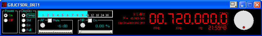
- Mute - Click the Mute checkbox on to mute the AF output
- Slider left to attenuate the output; slider right to amplify the output
- Volume knob counter-clockwise to decrease AF output level; clockwise to increase AF output level
- Mouse scrollwheel over the dB digits to decrease/increase the AF output level
The SDR may be tuned using several mechanisms.
- Mouse Scroll Wheel
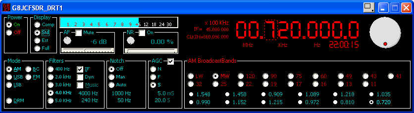
Move the mouse pointer over the digit you want to tune, eg if you want to tune in steps of 100Hz then move the mouse pointer over the 100' Hz digit. When you tune a digit, eg 100Hz, all digits to the right of that digit are set to zero. If you want to lock the tuning rate, then RIGHT Click over the digit you want to lock the rate at, OR LEFT click over the tuning rate indicator, ie the one showing x N KHz etc.
If you click on the words MHz, KHz, or Hz, just under the main frequency display, then the appropriate part of the frequency is set to ZERO, ie click on KHz, and the KiloHertz portion is zeroed.
- Keyboard Up and Down arrow keys
- Shaft Encoder - Alps P/N EC16B36104 available from http://rswww.com No. 265-1723 about EUR 4-00; see Using a Shaft Encoder to tune the G8JCFSDR.
- Soft Tuning Knob - hold down the left mouse button over the tuning knob and turn the knob - more of a gimmick than really useful, but for completeness here it is.
2) Select a preset by LEFT mouse click.
3) You can edit a Preset by RIGHT clicking over the preset you want to edit. (I will be extending this capability to editing the band selectors soon).
4) Pressing the Ctrl key whilst over a preset will toggle on/off the preset detail display panel
The Bandplans/presets are held in *.BPL files in the same directory as the program. If you add another .BPL the SDR will automatically find it the next time it starts up and add it to the list if available Bandplans.
- AM selects Amplitude Demodulation
- BC selects an alternative AM demodulation mechanism which sometimes sounds better for MW music stations
- USB selects Upper Sideband demodulation
- LSB selects Lower Sideband demodulation
- FM selects Narrow Band Frequency demodulation
- DRM tells the SDR to release the soundcard, & mute the output, so as to enable the use of external s/w such as dream.exe to demodulate the DRM signal - The tuning part of the G8JCFSDR is still fully functional
- Select the filter bandwidth appropriate for the demodulation mode desired. 400Hz is good for CW, 2.0KHz is good for SSB, 3,4,5 kHz are good for AM broadcasts.
- Click Music On for extended Bass response which is good for AM Broadcasts
- Click IF On for improved selectivity.
- Dyn is special kind of filter which automatically tracks the greatest amplitude peak frequency of the received signal, and sets the filter's centre to that peak in real-time.
- The G8JCFSDR provides fully adjustable filters. The adjustment precision is 10 Hz. To adjust the High frequency cut-off, place the mouse over upper Hz figures; use the mouse scrollwheel to roll the HF cutoff frequency up or down. To adjust the Low frequency cut-off, place the mouse over the lower Hz figures; use the mouse scrollwheel to roll the LF cutoff frequency up or down.
- To reset the filters to their preprogrammed default pass-bands, Right mouse-click over the cut-off adjust figures.
- Off - Switch off the Notch filter
- Man - Switch on Notch filter in Manual mode
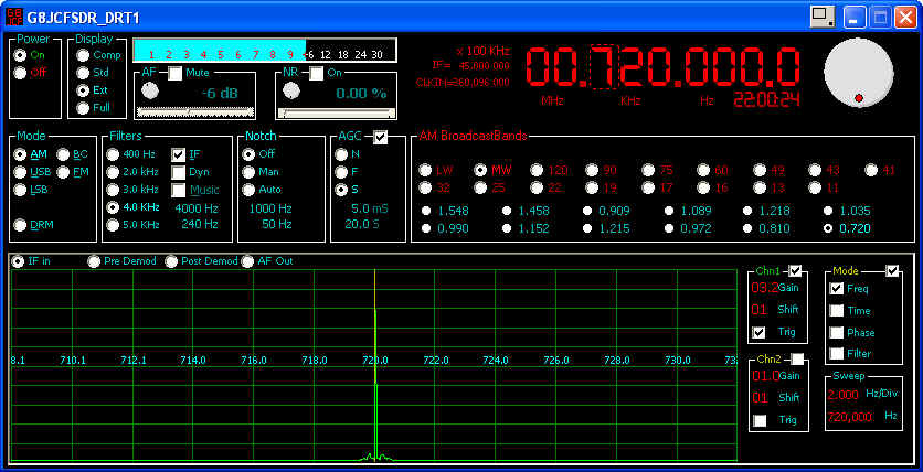
In Manual notch mode, the operator adjusts the notch centre frequency using upper Hz figures (mouse scrollwheel), and the width of the notch using the lower Hz figures (mouse scrollwheel). if the Spectrum display is enabled, the notch frequency will be shown as a red line, and if you select AFOut on the spectrum display, you will see the affect of the width adjustment - Auto - Switch on Notch filter in Automatic mode
In Automatic notch mode, the G8JCFSDR continuously and automatically adjusts the notch centre frequency in real-time to notch out the strongest frequency.
- AGC is turned On/Off by clicking on the AGC Check Box
- N - Normal AGC time constants
- F - Fast AGC time constants
- S - Slow AGC time constants - Best for SSB reception
- You can adjust the AGC Attack and Decay time constants using the upper and lower figure displays in the AGC box using the mouse scrollwheel.
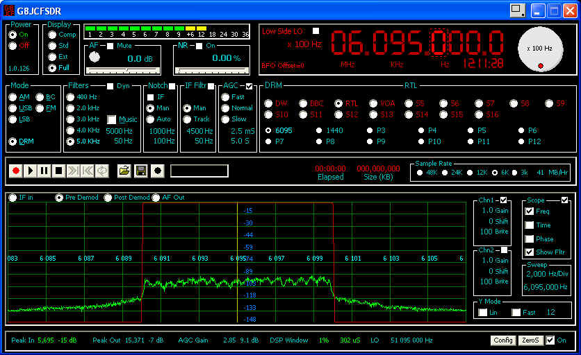
Button
A) Select audio devices
B) Set IF Frequency
C) Set DDS CLKIN
D) Calibrate DDS CLKIN
E) Select Parallel or Serial I/F to the h/w, Default is Parallel - so uncheck it if you haven't got a parallel cable
F) Select the COM port for Serial mode
G) Select if you want to use the Intel SPL instead of the G8JCF SPL (If you can find a copy of the iSPL to install)
- Freq - Select Spectrum Analyser mode
- Time - Select Oscilloscope mode
- Phase - Display Lissajous figures of Y1 and Y2, ie Y2 is used as the X sweep
- Filter - Display the filter passband as an overlay onto the received signals (only applicable in Freq Mode)